> For the complete documentation index, see [llms.txt](https://docs.vectra.ai/llms.txt). Markdown versions of documentation pages are available by appending `.md` to page URLs; this page is available as [Markdown](https://docs.vectra.ai/deployment/ndr-virtual-cloud-appliances/nutanix-vsensor/traffic-mirroring-deployment.md).
# Traffic Mirroring deployment
Deploying Nutanix vSensor VM using Traffic Mirroring to direct traffic at the vSensor capture port.
## Traffic Mirroring Deployment Overview
Prism Central is the only supported method for deployment using Traffic Mirroring as a steering method. Prism Central is required to create and manage Traffic Mirroring Sessions in the UI. Traffic Mirroring Sessions can also be created in the ACLI, but this is not in scope for this guide and Nutanix has stated to Vectra that ACLI access is planned to be removed in a future release and therefore, Vectra is not documenting CLI based Traffic Mirroring.
Below is an overview of the major steps:
{% stepper %}
{% step %}
#### [Create vSensor VM](#id-1.-create-vsensor-vm)
* One NIC will a standard NIC that will be used for management (MGT1).
* A special **Mirror Destination NIC** will be added to be used as the vSensor capture port. Only Mirror Destination NICs can be used as destinations in a traffic mirroring session.
* The disk size can be altered during deployment for 4, 8, or 16 core vSensors.
* 2 core vSensors do not need their disk size altered.
* If you miss this step, with the vSensor VM powered off, you can follow the instructions from [Increase vSensor VM Disk Size (if required)](https://docs.vectra.ai/deployment/ndr-virtual-cloud-appliances/nutanix-vsensor/pages/KHhOiBZnaHA2qlXjT8Yq#id-2.-increase-vdisk-size-vsensor-vm-if-required) to alter disk size after deployment or change the size by updating the VM in Prism Central UI.
{% endstep %}
{% step %}
#### [Set VM Affinity](#id-2.-set-vm-affinity)
Affinity should be set in Nutanix to keep the Vectra vSensor VM deployed on a specific AHV host.
{% endstep %}
{% step %}
#### [Create a Traffic Mirroring Session](#id-3.-create-a-traffic-mirroring-session)
This can also be done after initial vSensor configuration and pairing in Step 4 but if you don't have a traffic mirroring session configured, you won't be able to validate traffic.
There is no risk, just bear in mind that traffic that is mirrored to the vSensor before it is paired to the Brain will not be forwarded to the Brain appliance for processing.
{% endstep %}
{% step %}
#### [Perform Post Deployment Configuration](#id-4.-perform-post-deployment-configuration)
* Intial vSensor configuration at the CLI.
* Pairing the vSensor to your Brain appliance.
* Validate traffic is being captured by the vSensor.
{% endstep %}
{% step %}
#### Repeat as Needed
Add additional vSensors and create/update traffic mirroring sessions as required for your deployment.
{% endstep %}
{% endstepper %}
## 1. Create vSensor VM
Navigate in Prism Central to *Infrastructure → Compute → VMs → Create VM* and you will be presented with a four-page dialog to create the vSensor VM:
#### Configuration - Page 1
* **Name** – Use a name of your choice.
* **Description** – Optional.
* **Project/Cluster** – Set if required for your org.
* **Number of VMs**
* Normally 1 if deploying a single vSensor.
* This can be set to more than 1 if you are deploying multiple identically configured vSensors. The additional vSensors would be named with -1, -2, etc after the configured name.
* **VM Properties**
* Refer to [Nutanix vSensor Requirements and Performance](/deployment/ndr-virtual-cloud-appliances/nutanix-vsensor/introduction-and-requirements.md#nutanix-vsensor-requirements-and-performance) for vSensor specification.
* **CPUs** – Set to 2, 4, 8, or 16 based on the size vSensor you are deploying.
* **Cores** – Always set to 1.
* **Memory** – Set to 8, 8, 16, or 64 based on the size of vSensor you are deploying.
* **Advanced Settings** – Not required.
#### Resources - Page 2
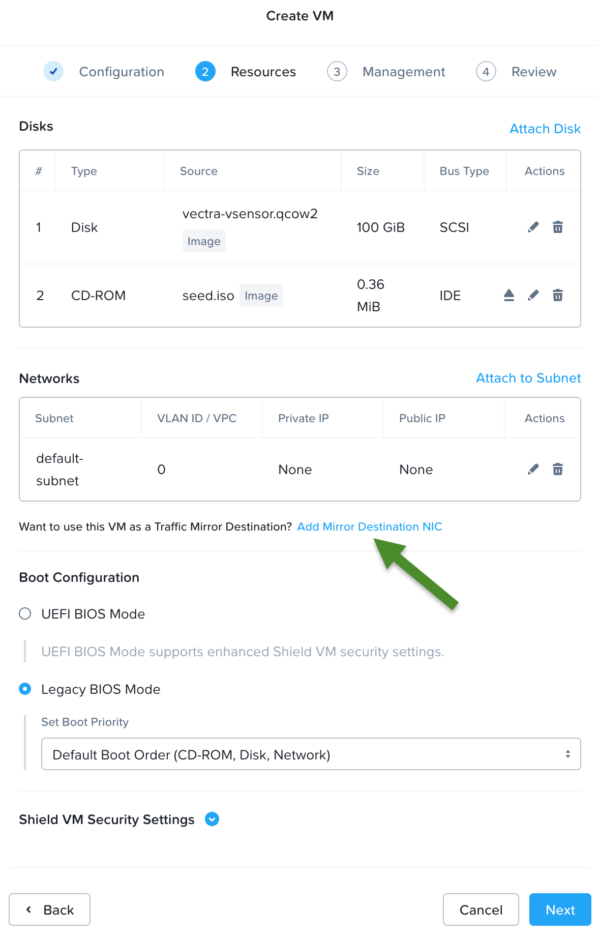
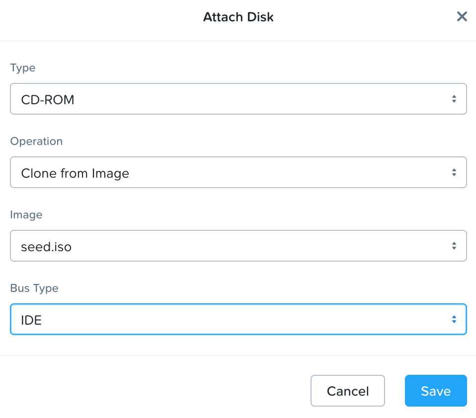
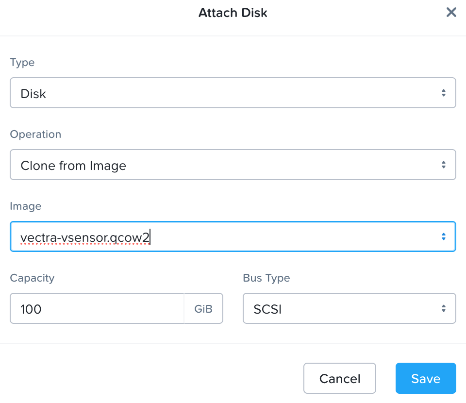
* **Disks** – Add the disks per the screenshots below, cloning them from the uploaded vSensor images.
* Disk size can be changed per the vSensor specifications to avoid doing it via [Increase vSensor VM Disk Size (if required)](https://docs.vectra.ai/deployment/ndr-virtual-cloud-appliances/nutanix-vsensor/pages/KHhOiBZnaHA2qlXjT8Yq#id-2.-increase-vdisk-size-vsensor-vm-if-required) after deployment.
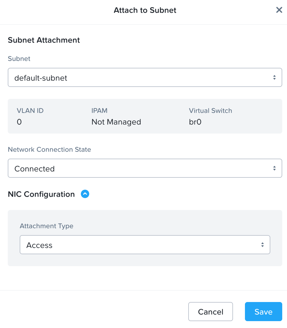
* **Network** – Attach to the subnet of your choice.
* This will be where the Management (MGT1) interface of the vSensor will be connected.
* Initially it will boot with DHCP, but this can be changed to static at the CLI of the vSensor.
* See [Initial vSensor configuration at vSensor CLI](/deployment/ndr-virtual-cloud-appliances/nutanix-vsensor/initial-vsensor-configuration-at-cli.md) for details.
* **Add Mirror Destination NIC** – Click here to add the NIC that will become the vSensor capture port.
* **Boot Configuration**
* This must be set to **Legacy BIOS Mode** with **Default Boot Order (CD-ROM, Disk, Network)**.
* The `seed.iso` (CD-ROM) is read during vSensor boot to help configure network adapters.
* **Shield VM Security Settings** – Not required.
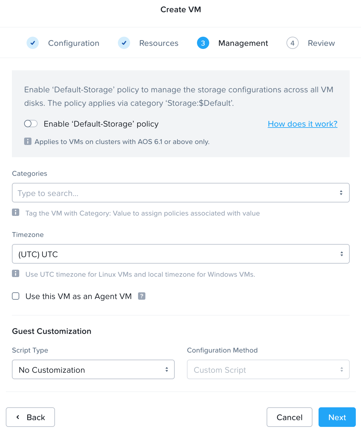
#### Management - Page 3
* **Enable ‘Default-Storage’ Policy**
* Whether you enable this or not will depend on your defaults.
* As per the [Nutanix vSensor Requirements and Performance](/deployment/ndr-virtual-cloud-appliances/nutanix-vsensor/introduction-and-requirements.md#nutanix-vsensor-requirements-and-performance):
* Vectra recommends that Sensors are configured to use storage local to the hypervisor and are not stored on a SAN. Vectra vSensors require extremely high throughput from their disk storage and this throughput cannot normally be sustained by SAN systems without impact to other SAN users.
* Also keep in mind that you will be pinning (setting affinity) for each vSensor to a specific node in each cluster.
* **Categories**
* Categories are not required for Traffic Mirroring deployment.
* **Timezone** – Configure per your standards.
* **Use this VM as an Agent VM**
* The vSensor needs to be set as an **Agent VM**.
* This can be enabled now, or set later at the CVM ACLI.
* **Guest Customization** – Not required.
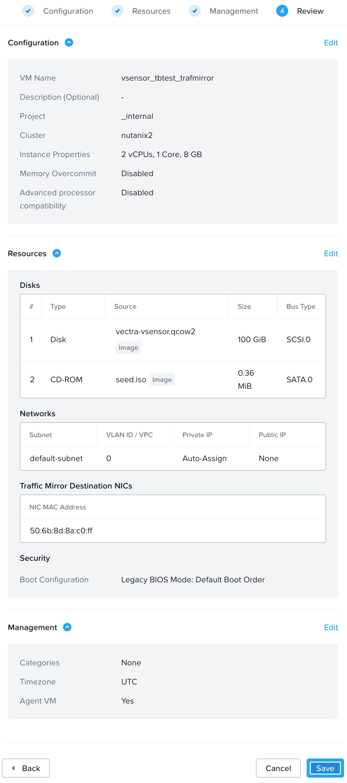
#### Review - Page 4
* Review the settings, go back and change anything if required, and when ready, click **Create VM**.
#### Screenshot Examples
Full Prism Central VM configuration example screenshots below. Click to enlarge any image.
Configuration - Page 1
Resources - Page 2
Adding seed.iso as CD-ROM on Resources - Page 2
Adding .qcow2 as Disk on Resources - Page 2
Attach to Subnet on Resources - Page 2
Management - Page 3
Review - Page 4
## 2. Set VM Affinity
Affinity ties the vSensor VM to a specific node so that is not moved from a node and setting it is a best practice
* This is setting an affinity to a specific node (also known as pinning).
* Since traffic mirroring sessions cannot mirror host ports across nodes, pinning the VM prevents the vSensor from moving to a location where the mirroring session would no longer function.
To set affinity using the ACLI.
* Log in to a CVM in your target cluster and access the ACLI.
* Execute the below ACLI command. `vSensor_Name` should be replaced by your vSensor name and `x.x.x.x` should be the IP of the node you are setting affinity to.
```
nutanix@CVM $ acli
vm.affinity_set vSensor_Name host_list=x.x.x.x
```
Affinity can also be set in the GUI without needing to find the IP of the node you are setting affinity to:
* Navigate in your Prism Element UI (for the cluster you are working on) to the VM table view, select your vSensor VM and click the “Update” button.
* Scroll down to the bottom and set the affinity to the specific node you desire.

## 3. Create a Traffic Mirroring Session
Please see [Traffic Mirroring](https://portal.nutanix.com/page/documents/details?targetId=Prism-Central-Guide-vpc_7_3:mul-traffic-mirror-pc-c.html) for full guidance from Nutanix with additional detail. This guide will contain only high-level steps for creating a session.
To create a Traffic Mirroring Session:
* In Prism Central, navigate to *Infrastructure → Network & Security → Network Services → Traffic Mirroring.*
* Click **Create Mirror Session**.
* On the first screen, give your session a name, optional description, choose the cluster, and virtual switch to use for the mirrored traffic.
{% hint style="info" %}
**Please Note:**
Nutanix recommends utilizing a non-default virtual switch with a Maximum Transmission Unit (MTU) configured between 1600 and 9000 for traffic mirroring to a destination on the remote host. You can also use the default virtual switch `VS0` for traffic mirroring with an MTU set to 1600 bytes. For more information on MTU, see [Requirements and Limitations of Flow Virtual Networking](https://portal.nutanix.com/page/documents/details?targetId=Nutanix-Flow-Virtual-Networking-Guide:ear-flow-nw-requirements-pc-r.html) and [Configuring Virtual Switch for VPC Traffic Types](https://portal.nutanix.com/page/documents/details?targetId=AHV-Admin-Guide:ahv-cluster-nw-create-uplinks-vpcs-ahv-t.html).
{% endhint %}
* On the second screen, you can choose the source types, host ports, and VM interfaces that you wish to mirror on the **Source** side, and on the **Destination** side you will choose the vSensor you are using as the destination and its **Mirror Destination NIC**.
* Only VMs with **Mirror Destination NICs** that are not already mapped will be shown as options.
* For **Direction**, typically you will want to choose **Both** to capture both ingress and egress traffic.
* On the third summary screen, validate your choices and **Create and Enable Session**.
* Repeat these steps for other vSensors as required. Sessions can be updated by editing them.
## 4. Perform Post Deployment Configuration
The vSensor is now deployed in Nutanix and you can move on to [Post deployment configuration](/deployment/ndr-virtual-cloud-appliances/nutanix-vsensor/post-deployment-configuration-shared-for-all-deployment-types.md) or repeat vSensor deployment and traffic mirroring configuration as required for your deployment.
---
# Agent Instructions
This documentation is published with GitBook. GitBook is the documentation platform designed so that both humans and AI agents can read, navigate, and reason over technical content effectively. Learn more at gitbook.com.
## Querying This Documentation
If you need additional information that is not directly available in this page, you can query the documentation dynamically by asking a question.
Perform an HTTP GET request on the current page URL with the `ask` query parameter, and the optional `goal` query parameter:
```
GET https://docs.vectra.ai/deployment/ndr-virtual-cloud-appliances/nutanix-vsensor/traffic-mirroring-deployment.md?ask=&goal=
```
`ask` is the immediate question: it should be specific, self-contained, and written in natural language.
`goal` is optional and describes the broader end goal you are ultimately trying to accomplish on behalf of the user. GitBook uses it to tailor the answer towards what is most useful for that goal.
The response will contain a direct answer to the question and relevant excerpts and sources from the documentation.
Use this mechanism when the answer is not explicitly present in the current page, you need clarification or additional context, or you want to retrieve related documentation sections.